

DMC 85 (FD) monoBLOCK
The monoBLOCK series has a machine concept for every sector
Max. X-axis stroke
37 in.
935 mm
Max. Y-axis stroke
33 in.
850 mm
Max. Z-axis stroke
26 in.
650 mm
Max. workpiece diameter
31 in.
800 mm
Max. workpiece height
23 in.
590 mm
Max. workpiece weight
2,205 lbs.
1,000 kg
Control & software alternatives
SIEMENS
HEIDENHAIN
Highlights
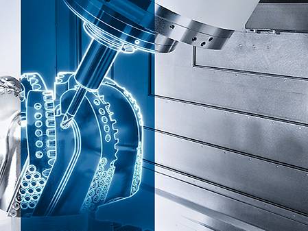
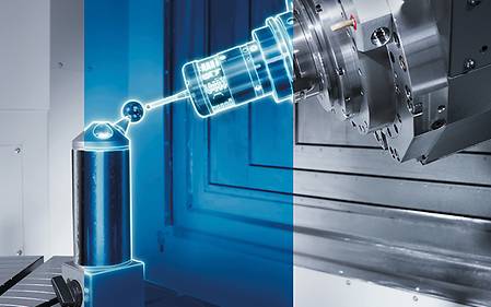
monoBLOCK – Die & Mold Application

Ergonomic
- Unrestricted accessibility from the front to the working area
- crane loading from above up to the centre of the table
- Footprint of just 26 m² including chip conveyor and coolant system
Precise
- Comprehensive cooling measures, high-performance coolant unit and multi-sensor compensation as standard
- From 5 µm positioning accuracy in standard
- Stiff construction with high static masses and balanced moving parts
Versatile
- Full package including swivelling rotary table and chip conveyor
- Also available in mill- /turn - version for complete machining with 2,050 Nm table-torque
- Automatic pallet changer for a total of three pallets
- 1,000 kg maximum load, with crane loading into working area up to 1,500 kg and workpieces up to ø 800 mm
monoBLOCK Excellence Factory

")

Application Examples
Automation
Standard automation and customized solutions in the VERTICO design
Automation is a key element of digital production. Every DMG MORI machine can be upgraded with standard automation or with a customized automation solution for flexible manufacturing systems:
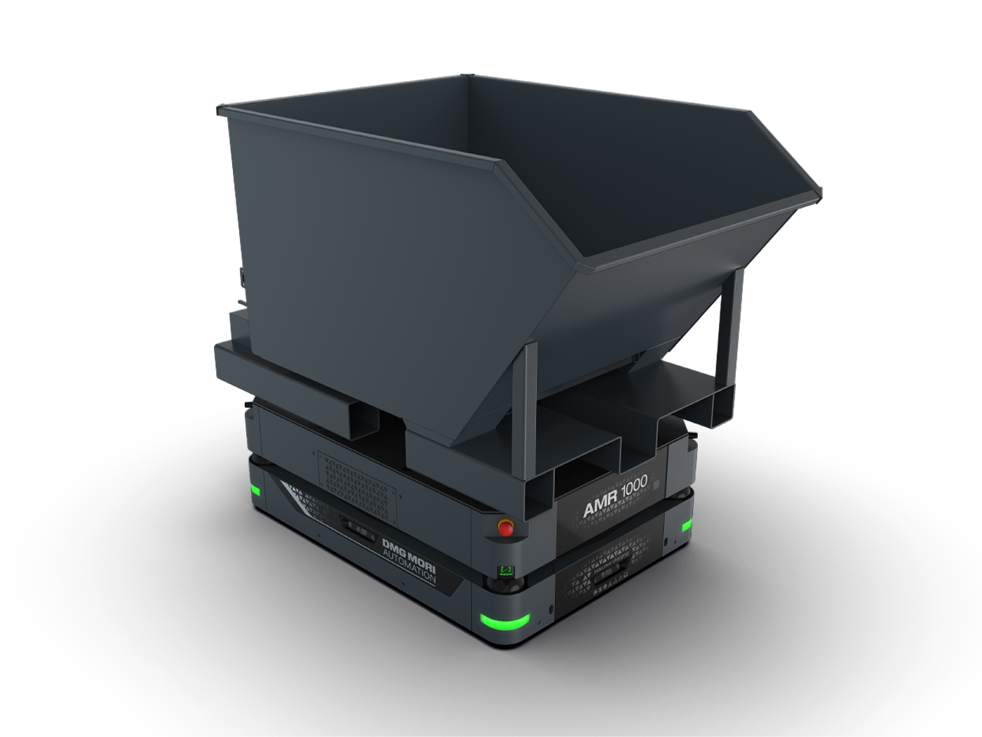
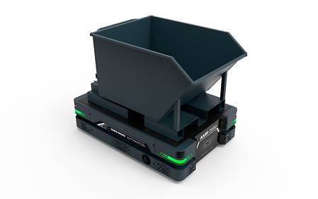
AMR 1000

Holistic automation on the shop floor
- Collaborative automation solution with free layout design
- Omnidirectional movement for minimal space requirements (turning radius 0m)
- Basis for additional tasks, e.g. B. tool handling, chip disposal, etc.
- Material transport, pallet size 800x600 mm to 1,100x1,100 mm, or 1,200 x 800 mm
- Maximum transport weight of up to 1,000 kg
- Security based on Sick and Siemens technology
Highlights
AMR 1000 Material

- Autonomous transport of material pallets
- Transport of different load carriers
- Integration into DMG MORI automation systems for workpiece handling – exchange of finished part and raw part pallets
- Integration into existing processes
- Scalable and expandable at a later date
AMR 1000 chips
- Autonomous transport of chip containers
- Automatic transport order from the master computer
- Extended autonomy of the machine tool
- Material and chip transport can be combined
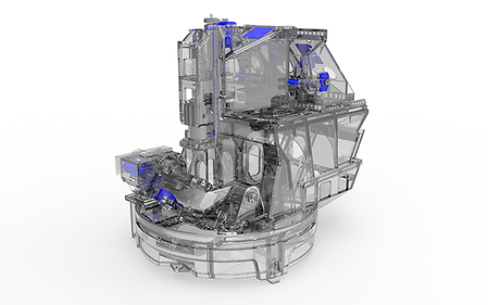
RPS monoBLOCK

RPS 3 / 6 - Machine-integrated automation with minimum space requirement
- Unmanned shifts due to circular storage system with 3 or 6 pallets
- Handling of workpieces up to ø 800 × 600 mm, 800 kg max.
- Reduction of non-productive time due to loading and unloading during production
- Flexible production of different parts
- Pallet Master – for convenient and simple control of the automation directly via the machine control
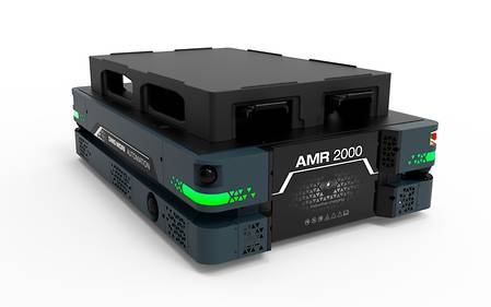
AMR 2000
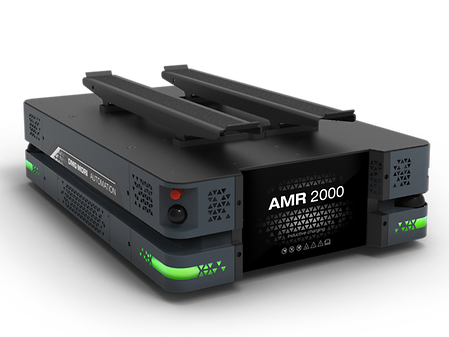
Holistic automation on the shop floor
- Collaborative automation solution with free layout design
- Omnidirectional movement for minimal space requirements (turning radius 0m)
- Basis for additional tasks, e.g. B. tool handling, chip disposal, etc.
- Material transport from Euro pallets 1,200 x 800 mm
- Maximum transport weight of up to 2,000 kg
- Security based on Sick and Siemens technology
Highlights
AMR 2000 Material
- Autonomous transport of material pallets
- Transport of different load carriers
- Integration into DMG MORI automation systems for workpiece handling – exchange of finished part and raw part pallets
- Integration into existing processes
- Scalable and expandable at a later date
AMR 2000 chips
- Autonomous transport of chip containers
- Automatic transport order from the master computer
- Extended autonomy of the machine tool
- Material and chip transport can be combined
AMR 2000 tool handling
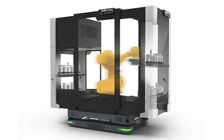
- Tool identification in the standard
- Autonomous transport and exchange of tools between machines and tool storage systems
- Max. tool dimensions ø 280 / 400 mm
- Max. tool weight 30 kg
- Transport weight 720 kg (24× 30 kg)
- Maximum number of tools: 24 pcs
PH-AMR
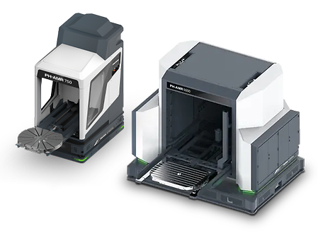
Pallet automation with maximum flexibility through free layout design
- Modular concept with flexible layout design
- Driverless transport systems without guide rails or tracks
- Collaborative: Man and machine in one system
- Navigation through natural navigation
- Pallet sizes from 500 × 500 mm to 1,600 × 1,250 mm
- Workpieces up to 5,000 kg and ø 1,600 mm
Highlights
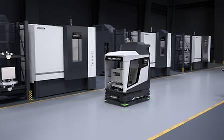
Free accessibility
- Best visibility into the workspace at any time
- Manual or crane loading still possible
- Collaborative system – man and machine in one system
Modular concept with free layout design
- No safety housing for the automation system necessary
- Free positioning possibility of the individual modules
- Subsequent integration into existing production
Simple expansion of automation system
- Additional shelf modules to increase the number of storage places
- Additional AMRs can be integrated in the system
- Machines with an automation interface can be integrated very quickly afterwards
Minimum space requirement
- Free pallet handling system without fixed installation requirements on hall floor
- AMR paths remain walkable and passable
- Laser scanners guarantee personal protection in driving direction
- Omnidirectional movement for minimum space requirements (turning circle 0m)
- Flexible automation concept - Automation of different machine types with one system
Control & Software
HEIDENHAIN TNC7

- Individually customizable user interface with freely configurable windows
- Intuitive setup of workpieces with smart probing functions and graphically supported alignment of clamping devices
- Simple programming in HEIDENHAIN conversational programming or according to DIN/ISO
- Extensive machining and touch probe cycles
- High-end performance for perfect surfaces and maximum accuracy
- Dynamic collision monitoring and realistic for more safety
- HEROS operating system based on Linux for maximum IT security
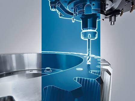
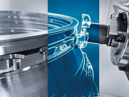
Interpolation turning 2.0 – turning recessing cycle
- With interpolation turning, the tool cutter follows a circular movement, where the cutter is always oriented towards the center Of the circle.
- Possible for external and internal machining
- Synchronization and tool path controlled by the cycle
- NEW: in version 2.0 complex turning contours are possible (currently only available on the DMU 50, other machine types will follow)
Highlights
Customer benefits
- Easy manufacturing of sealing surfaces where milling operation might not be possible.
- Complete component processing in one clamping possible
- Reduced investment costs for tools
Maintenance Package i4.0
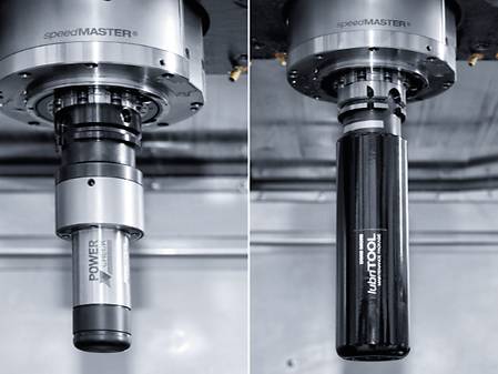
- Automatic recognition of tool pull-in force for consistently high process stability.
- Predefined cycle for automatic lubrication, every 75h or after 20,000 tool changes.
- Detection of leakage and measuring of usage of pneumatics system.
Highlights
Customer Benefits
- Efficient and timesaving lubrication without operator intervention
- High transparency by displaying the lubrication cycles and the current pull-in force.
- Data recording in combination with the optionally available Condition Analyzer for additional analyzes of air consumption and changes of the pull-in force
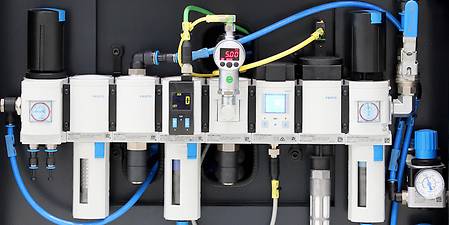
Detection of leakage and measuring of usage of pneumatics system.
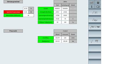
Simple query of the monitoring parameters and the current pull-in force.
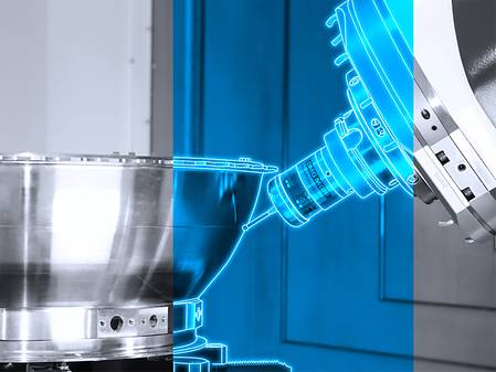
Excentric turning and milling
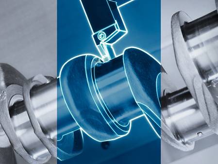
- Superposition of the turning movement by additional X- and Y-traverses
- Applicable for turning and milling
Highlights
Customer Benefits
- Eccentric geometries easy to manufacture
- Exact axis coupling and synchronization in the background
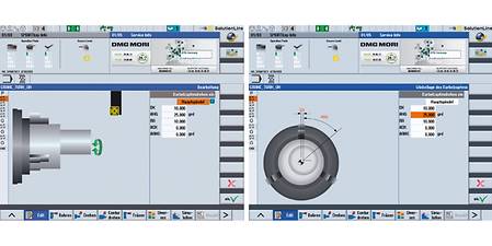
Left : Enter the parameters for the position of the external workpiece area. / Right : Graphical representation of the position within the workpiece.
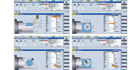
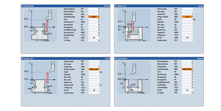
Efficient Production Package
- Solutions for a safe process and for the efficient use of important machining steps
- Applications: cone cleaning, tool data monitoring, safe withdrawal movement, tapping, deep hole drilling, external thread and spigot milling, internal thread and circular milling, reverse countersink cycle
- 12 stored machining strategies for stock removal, deep hole drilling, Pocket milling machines*
Highlights
Customer Benefits
- Runtime optimization according to individual application
- Safe retraction after program break
- Tool data monitoring
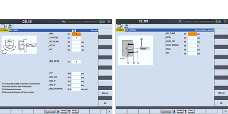
Left : Input mask for universal cycle pocket milling. / Right : Input mask for tapping cycle
Tilted Measuring Cycle
- Measuring with tilted tool axis
- Dialog-guided programming of the measuring cycles
- Positioning of the measuring points with rotary axis
Highlights
Customer Benefits
- Increase in component accuracy
- Reduction of set-up time
- Collision-free measuring thanks to tilted tool axis possible
- Further processing of the measurement results
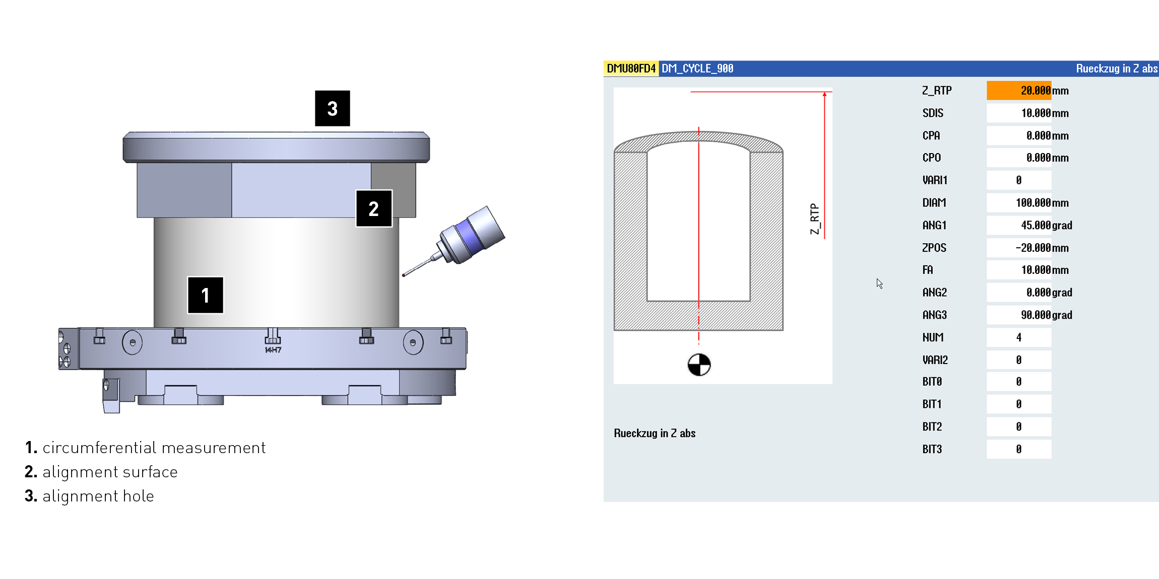
Left : 1. circumferential measurement, 2. alignment surface, 3. alignment hole / Right : Dialog-guided programming
L-Measuring probe packet

- Measurement of webs and grooves on components
- Measurement of diameter in difficult to access places
- Available with manual and retractable Calibration unit Package content
- L-Measuring probe according to Customer-specific design
Highlights
Customer Benefits
- Flexible application possibilities
- In process measurement

Left : Semi-automatic Measurement solution. / Right : Automatic measurement solution.
Application Tuning Cycle
- Process-oriented adjustment of the feed rate n relation to the table loading
- Minimization of machining time with maximization of the component quality
- NEW: Now also available for CTX TC. Ideal machining result with the highest machine dynamics*
*without consideration of feed weight
Highlights
Customer Benefits
- User friendly setting of the machine dynamics with included DMG MORI knowhow
- Time saving in roughing
- High surface finish during finishing
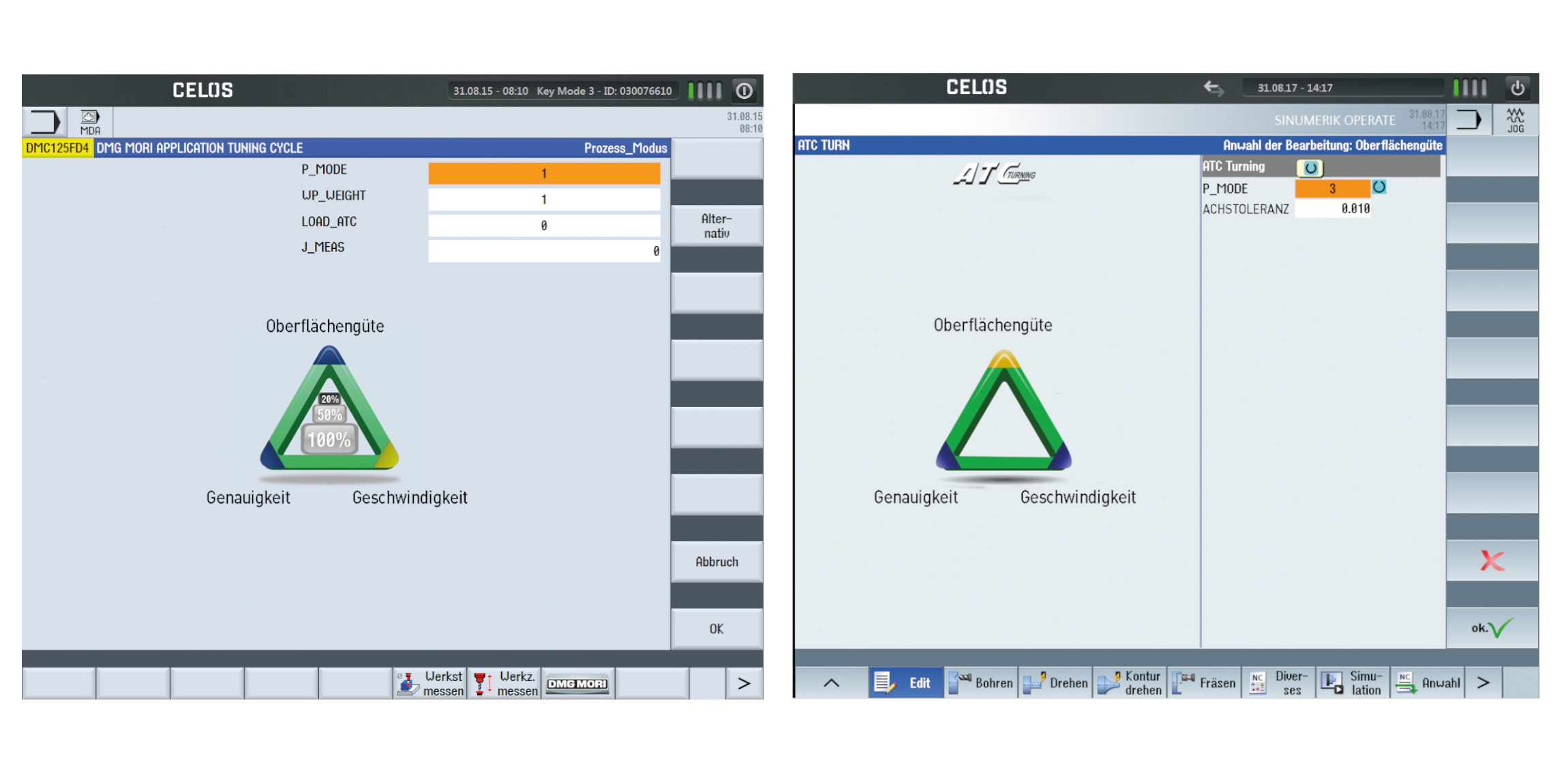
Left : ATC 2.0 – Milling: Consideration of table loading. / Right : ATC – Turning: for CTX TC for easy adjustment of the machine dynamics.
angularTOOL
- Highest flexibility in the machining of structural components due to variable alignment of the angle head
- Automatic CAD / CAM programming
- Automatic calculation of the TCP and combination with existing control functions
Highlights
Customer Benefits
- Machining of inaccessible positions on the workpiece.
- Savings in non-productive time due to fewer tool changes
- High cost savings due to the use of fewer tools
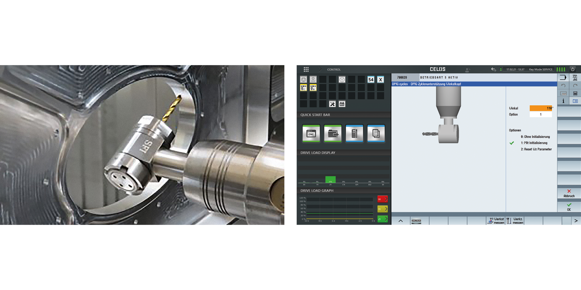
Left : Tool driven by KSS during drilling operation / Right : Parameter mask for variable angle setting
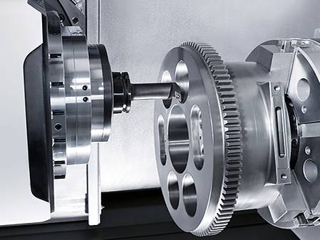
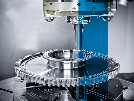
DMG MORI gearMILL
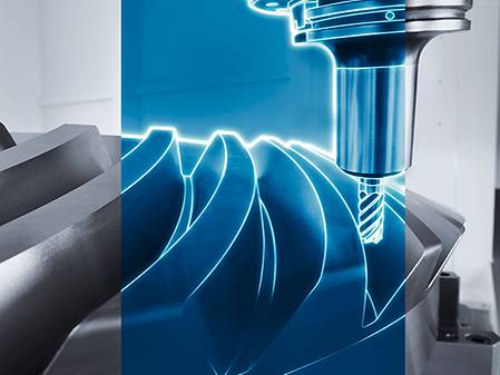
- Productive complete processing
- Cost-effective gear cutting on standard machine with standard tools
- Flexible for different gear geometries
- Quality inspection in the process
Highlights
Customer Benefits
- Program creation based on blank drawings and gear data
- Optimization of workpiece orientation e.g. after heat treatment
- Interface for coordinate measuring device (Klingenberg, Leitz, Zeiss)
Left : Input of the gear parameters for the geometry calculation of a spur gear. / Right : Grafische Betrachtung des Abwälzverfahrens.
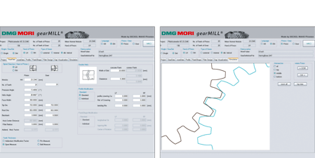
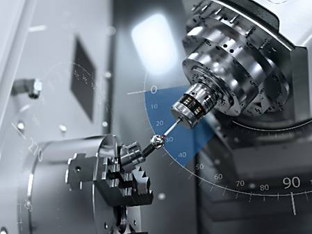
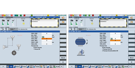
3D quickSET
Turning
- Measurement and correction of the position of turning and Pivot axes (C4, C3, B)
- Sag compensation possible
- Can be used in combination with standard probes from customers (recommended Renishaw, Blum)
Milling
- Toolkit for checking and correcting the kinematic accuracy of 4- and 5-axis machine configuration
- All head variations and table axes
Highlights
Turning Customer Benefits
- Reliable re-calibration of the machine before a highly precise processing
- Continuous documentation of machine accuracy
- No rejected parts due to unknown Geometric-deviations
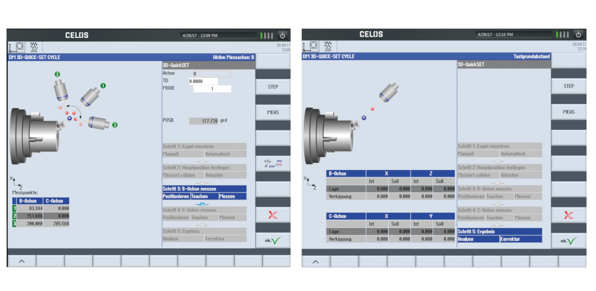
Dialogue-guided measurement of the B- and C-axis.
Milling Customer Benefits
- Periodic recalibration of the machine with comprehensive documentation
- Highest kinematic accuracy in self-regulation
Define kinematics head
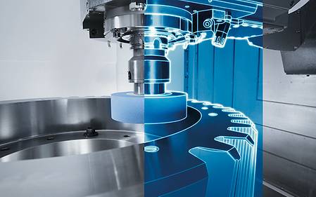
Grinding
Turning
- Turning, milling and grinding in one clamping
- Grinding cycles for internal, external and face grinding as well as dressing cyclesn
- Body-borne sound sensors for start-up and dressing
- Full integration of measurement module for relative and absolute LIVE-Measuring – parallel to main time
Milling
- Better surface quality through integration of the grinding technology
- Grinding cycles for internal, external and face grinding as well as dressing cycles
- Body-borne sound sensors for start-up and dressingn
- 1,300 l Cooling system with integrated centrifugal filter for The filtration of particles > 10 μ
- AKZ nozzle unit optionally available for best possible Flushing of the grinding gap
Highlights
Turning Customer Benefits
- Expansion of the technological limits of the CTX TC
- Surface accuracy < 0.4 μm
- Roundness < 5 μm
- Quality IT5 for ø > 30 mm
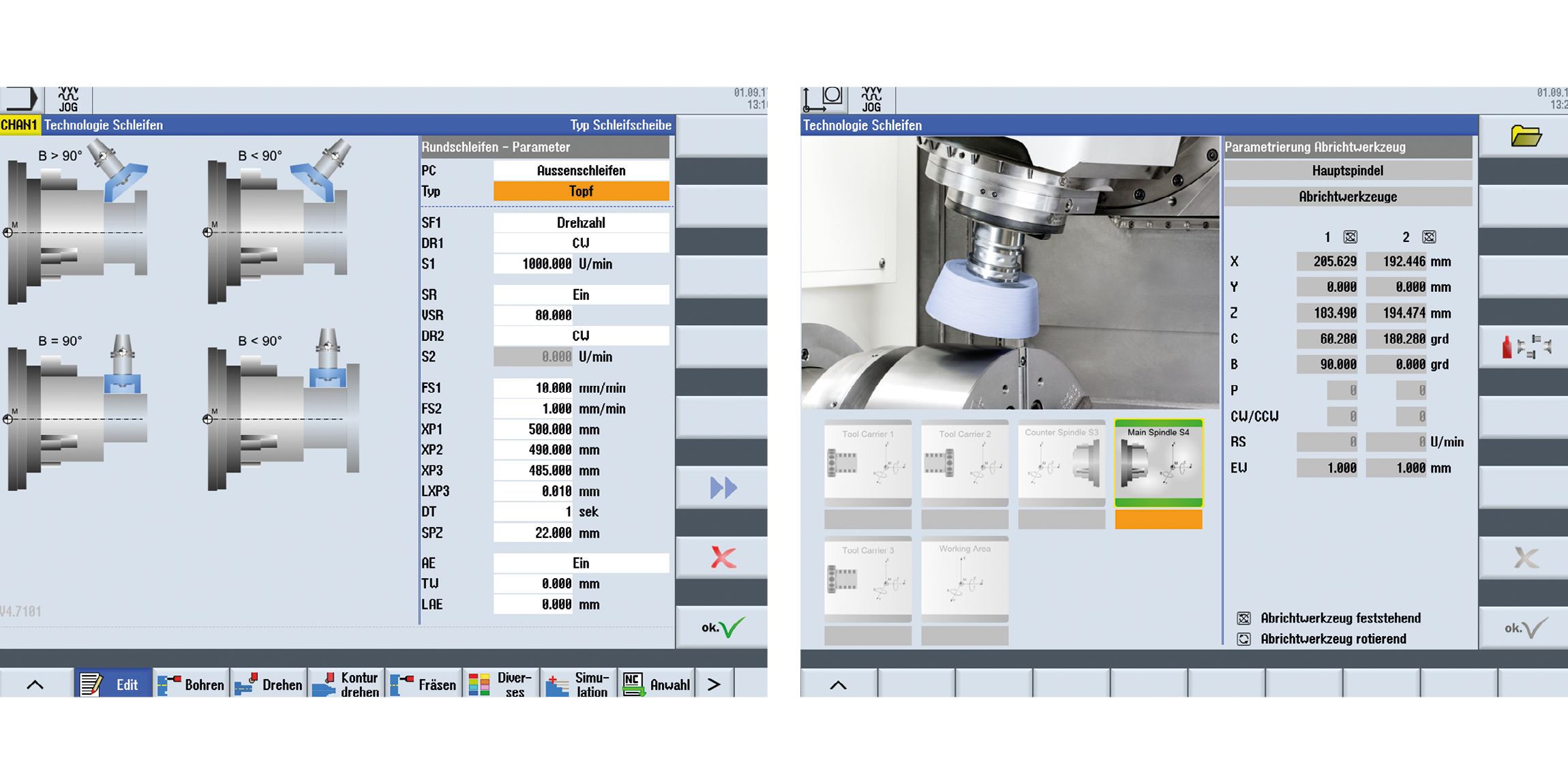
Left : External, internal and circular grinding. Grinding with straight / angle or cup disc. / Right : Dressing straight, angled or cup discs simply visualized.
Milling Customer Benefits
- Surface accuracy < 0.4 μ
- Roundness < 5 μ
- Quality 5 for ø < 120 mm
- Quality 4 for ø > 120 mm
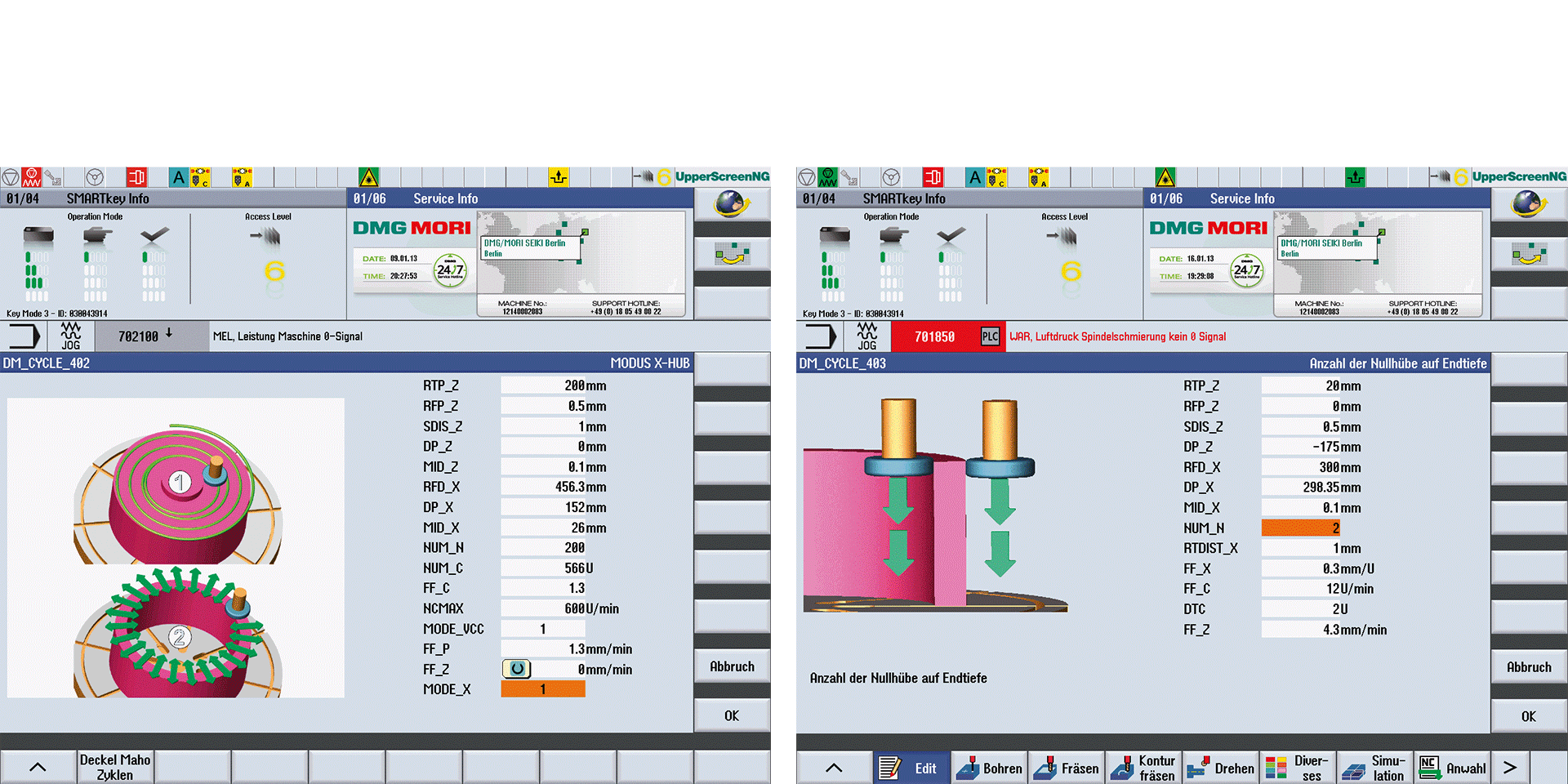
Left: Spiral plane grinding or osscillating plane grinding. / Right: Longitudinal grinding.
MPC 2.0 – Machine Protection Control
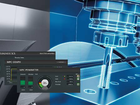
- Vibration monitoring in the process
- Rapid shutdown in case of a crash
- Manual retraction even in swiveled machining plane
- NEW: Torque monitoring
- New: Recommended with Protection Package for CTX TC machines
Highlights
Customer Benefits
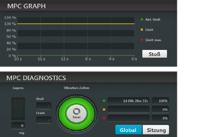
MPC Graph: current and learned process values. / MPC Diagnostics: stock condition, number of impact and crash.
- Avoiding tool breakage
- Increase in machine availability
- Damage reduction
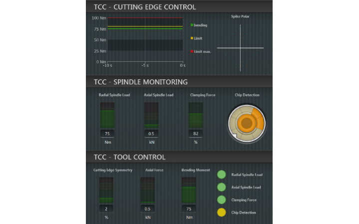
TCC – Tool Control Center
- Chip detection on plan pad and tool cone
- Monitoring of pull-in force
- Cutting edge control in process by symmetry monitoring of the bending moment per cutting edge
- Visualization of the bending moment over time via Graph
Highlights
Customer Benefits
- Tool and workpiece protection
- Optimized tool process
- Monitoring of the radial and axial spindle load depending on the actual pull-in force
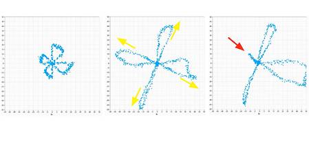
Left: NEW; Middle: Wear; Right: Cutting edge break
VCS Complete
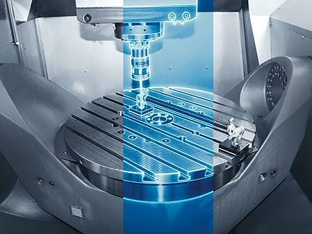
- Geometric fingerprint of the machine Volumetric calibration at the touch of a button
- Detection and compensation of geometrical, positioning and angular errors of all axes
- Easy handling and implementation by the customer directly at the machine
Highlights
Customer Benefits
- Regular compensation of the machine geometry over the entire life cycle of the machine
- Dialogue-led operation for easy and fast handling
- Data recording for further analysis
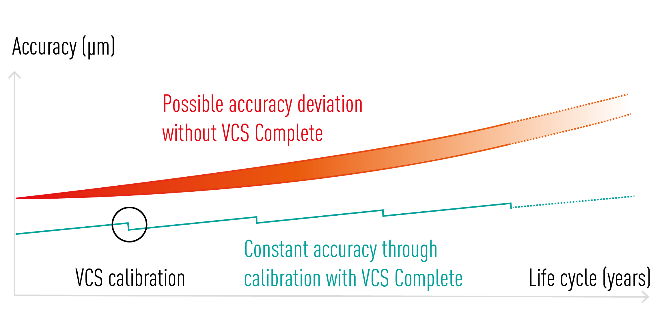
Possible accuracy deviation without VCS-Complete.
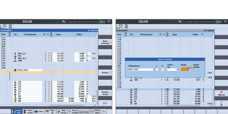
gearSKIVING 2.0
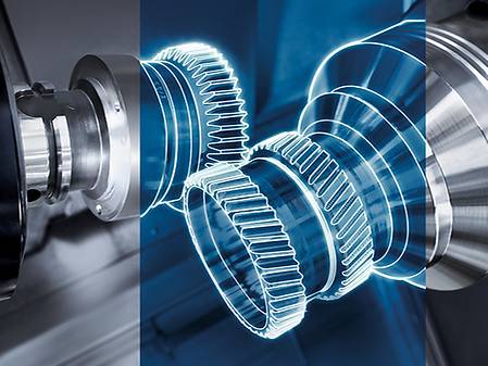
- Straight and helical external or internal spur gears and splines
- Arrow teeth with tooth offset Turn-mill machines
- Ball-shaped toothing by mathematical transformation of the 6th virtual axis
Highlights
Customer Benefits
- Internal toothing without angular head possible
- Short processing times, 10 x faster than shaping
- Synchronization and tool path controlled by the Cycle
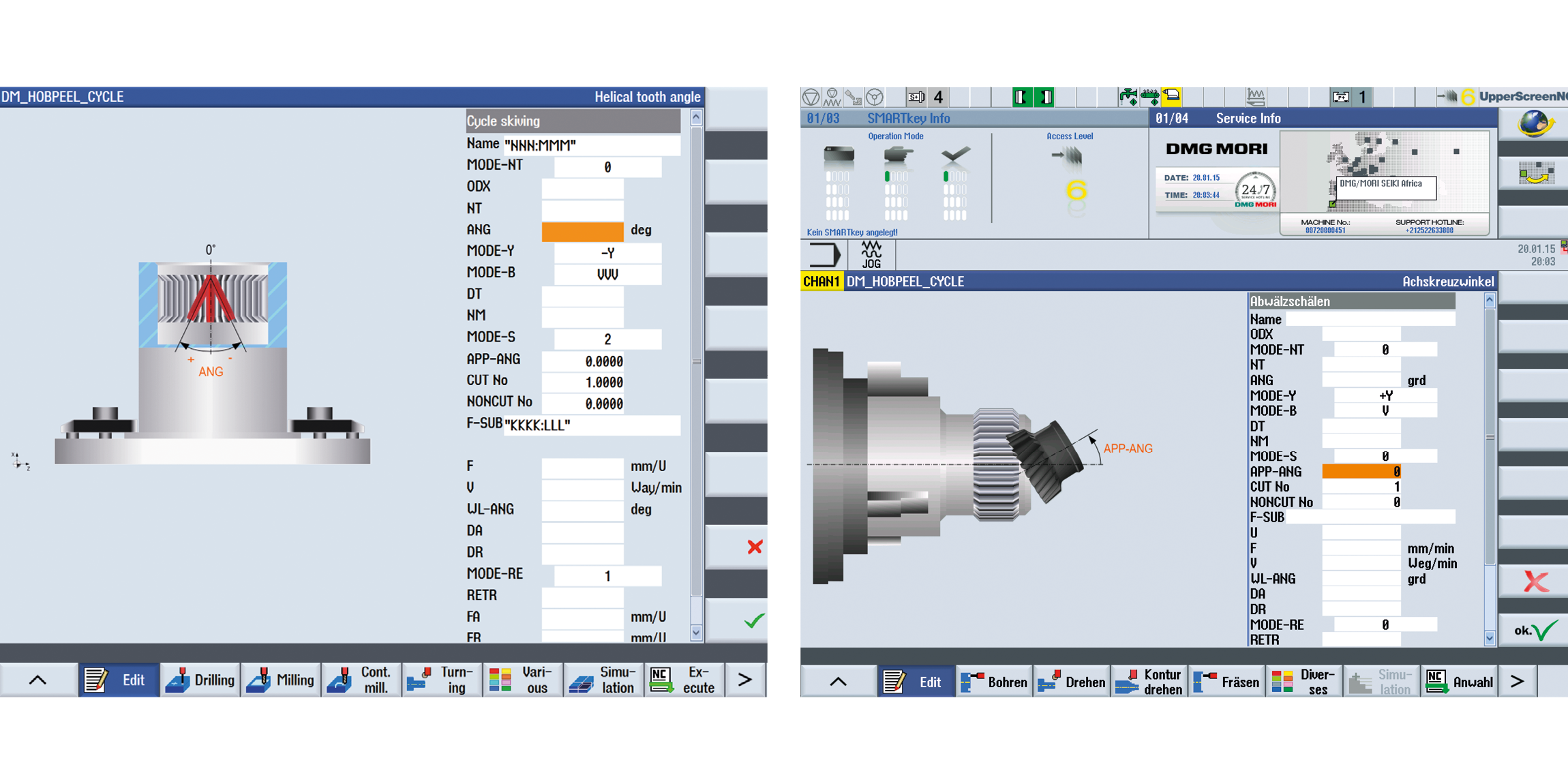
Left : Inside gear profile machining. / Right : Outside gear profile machining.
In-Machine Tool Balancing
- Balancing of tools in the machine for high surface requirements and machine protection
- Checking the balancing quality of the spindle
- Balancing quality up to 0.3 g/mm
Highlights
Customer benefits
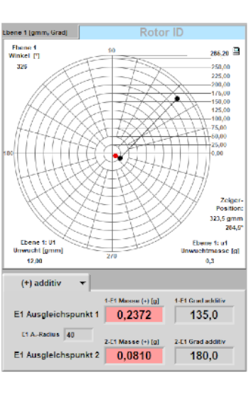
User Interface
- Better surfaces due to balancing of the entire system in the clamped state
- Balancing of the tool under machining conditions (machining position -vertical / horizontal, with / without internal cooling supply, speed)
- Economical, as no external balancing device is required
User Interface
Multitool
- Efficient use of multi-tip turning tools with more than one cutting edge on turn & mill
- Several "sister tools" on one main tool holder
Highlights
Customer Benefits
- Reduction of tool change times
- Saves tool magazine space
Service & Training
Downloads & Technical Data
Workpiece
Max. workpiece diameter
31 in.
800 mm
Max. workpiece height
23 in.
590 mm
Max. workpiece weight
2,205 lbs.
1,000 kg
Work Area
Max. X-axis stroke
37 in.
935 mm
Max. Y-axis stroke
33 in.
850 mm
Max. Z-axis stroke
26 in.
650 mm